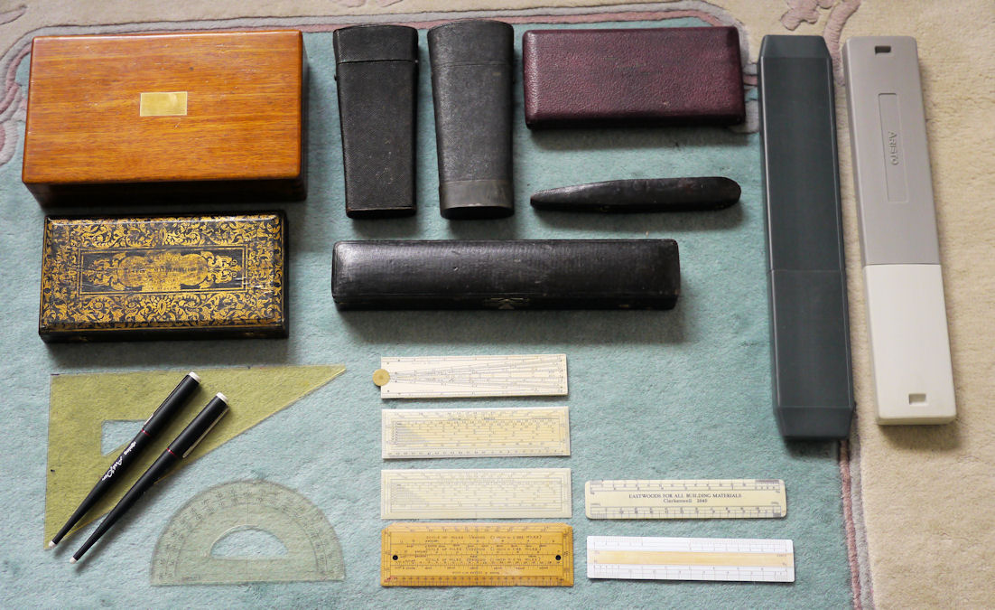
My Drawing and Calculating Instruments
From the mid 16th century until the 1970s all architectural and engineering drawing was done manually by using pencil and pen with the aid of drawing and other technical instruments. Today most technical drawing is done with CAD and the great instrument manufacturers have all but disappeared and the tools of yesteryear have now become museum exhibits and prized collectors' items. Here is my own collection which I started with my own modest tools, click on any one for a full description.
Click on an implement for a full description
The development of the drawing compass
The development of the bow compass
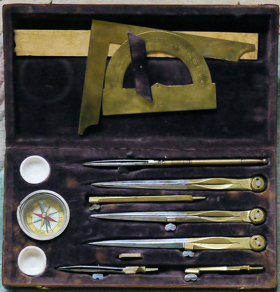
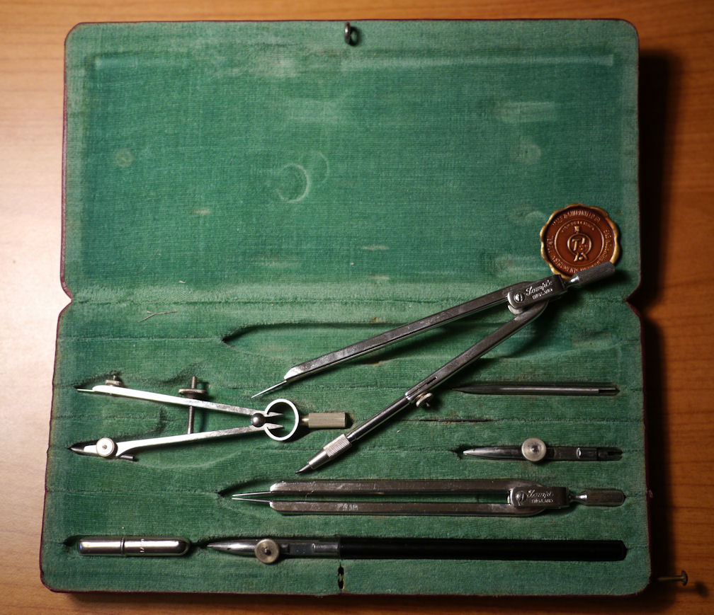
German 18th century etui of instruments in brass and steel in a leather bound case with ornate gilded decoration. On the lid is the legend ETUIS DE MATHEMATIQUE MANUFACTURE POUR DESSINS ARCHITECTURE ET BUREAU (Case of mathematical [instruments] manufactured for architectural and office drawings). There is a small printed label under the case: "L. E. W. Schwar - Kiel", probably the dealer rather than the maker. In the 18th century Kiel was a small port in the Danish crown's duchy of Schleswig-Holstein with a German minority population.
The contents are:
- Main compass (133 mm) with three inserts: divider, pencil, and ink points.
- Compass extension bar (75 mm).
- Pair of dividers with screw for fine adjustment (131 mm).
- Pair of dividers with fixed points (130 mm).
- Drawing pen.
- Adjusting key for the compasses.
- 7 inch walnut straight edge, one end with curves.
- Brass two-bladed set square, appoximately 0.5 mm thick.
- Brass engraved protractor, also appoximately 0.5 mm thick.
- Glass covered magnetic compass.
- Two small fine china porcelain dishes for mixing inks.
These are handmade instruments in a slim ornate travelling case.
 Return
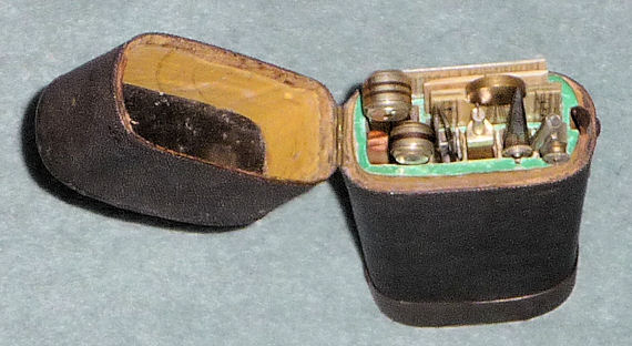
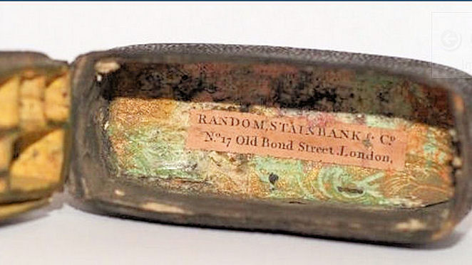
A pocket case of 6-inch English drawing instruments, late 18th century, in a black shagreen. Maker unkown, but with the dealer's label inside the case lid: Random, Stainbank & Co. No. 17 Old Bond Street, London, a firm of print sellers and publishers; the manufacturing end of the brass trade was dispersed in multiple little businesses and it was rare for them to put their names on their products.
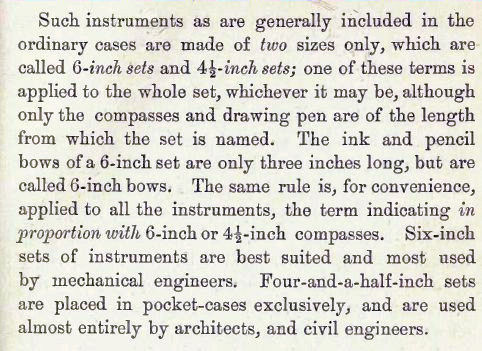
The case design with tightly packed instruments was very popular and was to endure for almost a century. Now dubbed etuis, they were originally called pocket magazine cases and were made in two sizes, 6-inch sets and 4½-inch sets. The latter, according to William Ford Stanley, were used entirely by architects and civil-engineers and the 6-inch sets by mechanical engineers. The bows of a 6-inch set were only 3 inches long, but they were still called 6-inch bows.
 A Descriptive Treatise on Mathematical Drawing Instruments - 1878
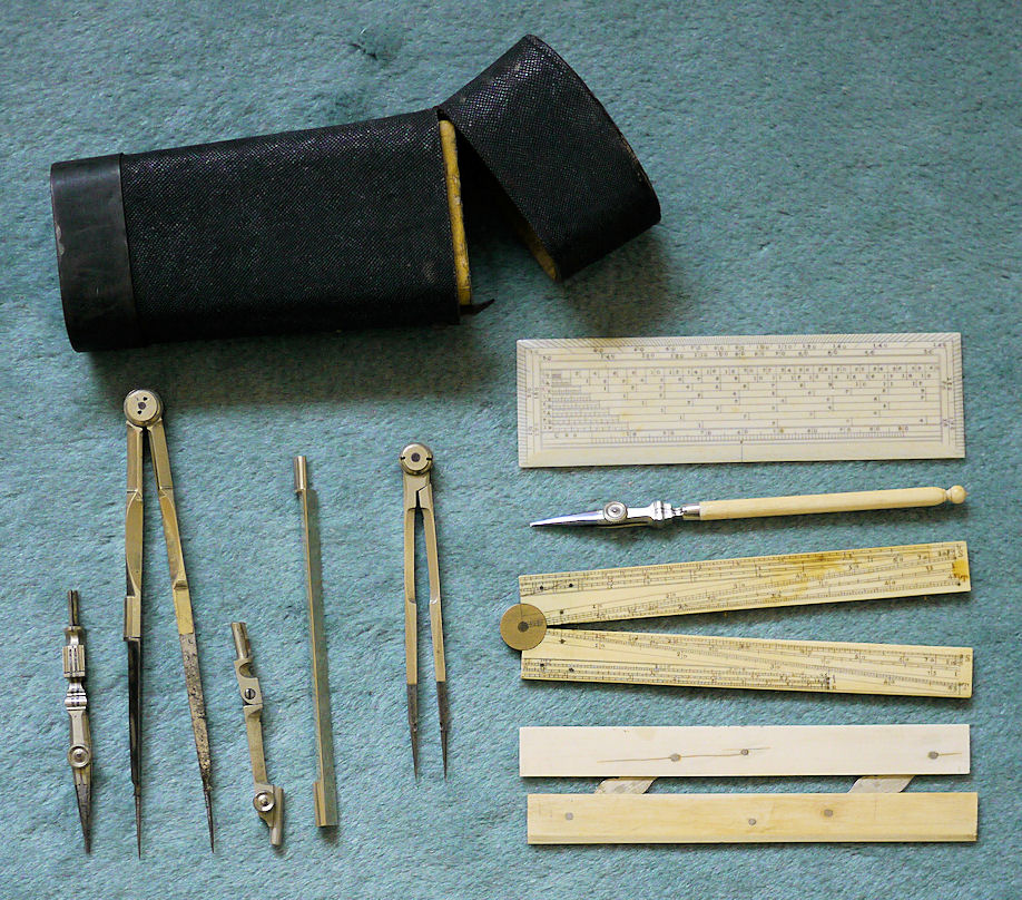
Contents:
- Main compass, brass long-joint interleaved with steel, (160 mm) with four inserts for crayon (pencil), ink, dotting wheel, and divider.
- Pair of dividers, matching main compass (130 mm).
- Drawing pen.
- Small ink compass.
- Boxwood scale ruler. It has two sets of decimal diagonals and has a further nine scales on the other side.
- Boxwood sector, with brass locating points.
- Brass engraved protractor 1.5 mm thick, more substantial and better made than the German 18th century one from Kiel.
The scale ruler, only 2 mm thick, has six tiny brass inserts for locating the anchor leg of measuring dividers (shown enlarged).
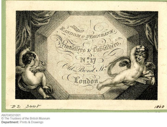
Trade card of Random and Stainbank, now in the British Museum
Return
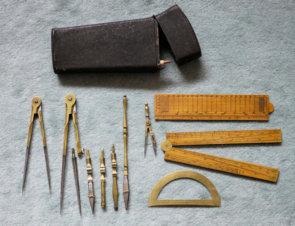
An etui of English 6-inch drawing instruments, electron, ivory, and steel circa 1860-1870 consisting of:
- Compass (158 mm) with a set of three inserts: divider, pencil, and ink points.
- Compass expansion bar (114 mm).
- Pair of electron dividers with fixed steel points (114 mm); contemporary with the rest of the set but not of the same high quality.
- Ivory and steel drawing pen.
- Ivory sector.
- Ivory parallel lines ruler.
- Ivory scales ruler.
At this stage most drawing instruments were made of electron rather than brass, which was now confined to the cheapest tools. Electron, now known as nickel silver, is an alloy of copper, zinc, and nickel; it had first been called German silver. The terms first appeared in English in the Technology Repository in 1829 in an article under the heading On the preparation of German silver, packfond, argenton, or electrum: a new metallic alloy. Regarding drawing instruments, it was in common use in Britain and mainland Europe by 1850 and in the 5th edition (1878) of his A Descriptive Treatise on Mathematical Drawing Instruments William Ford Stanley, the drawing instruments maker, says
The metals generally used in making drawing instruments are brass, electrum, or silver, .... Silver is littled used of late years, being costly and possessing little merit over electrum, which is at present the most popular.
It follows from this that no genuine 18th century or early 19th century instrument was made in nickel silver, all were brass or more rarely silver. Maya Hambly in her Drawing Instruments, 1580-1988, page 28, says thatElliott & Sons is known to have used this alloy in 1835 and Watkins & Hill, instrument makers of Charing Cross, refer to it in 1832 as a new white-metal not liable to tarnish ...
But this appears to be wrong, Elliott & Sons wasn't in existence in 1835. Hambly did not give her sources, but according to the Directory of British Instrument Makers 1550-1851, published by the National Maritime Museum, Wm. Elliott & Sons, 56 Strand, London, were only trading under that name from 1850 to 1853. They succeeded the business (1804-1849) of William Elliott, 268 High Holborn, London. It was a partnership of William Elliott and his sons Frederick and Charles, and on the death of the senior partner, their father, in 1853 Elliott & Sons became Elliott Brothers.
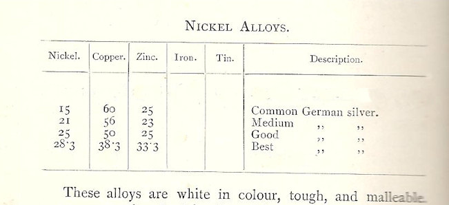
More generally, aside from drawing instruments, the term used was German silver. A table in Metallurgy by E. L. Rhead, published in 1895, gives the alloy's composition, followed by a more precise description of electrum in 1912:
From this it would appear that the quality of German silver used in drawing instruments was that rated as 'good' in Rhead's table. But it wasn't until the 1860s that it started to be called nickel silver.
Return
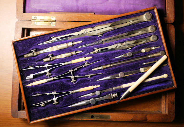
This is a standard full-set of drawing instruments, typical of late Victorian and Edwardian boxed sets. Probably imported from France but sold under the name and brand of Alex Mathieson & Son. This was common practice in the 19th century by all the major instrument makers. They are top quality, made in electron (nickel silver), ivory, and steel. The largest compass is stamped MATHIESON EDINBURGH and the lettering B.S.G.C.G. is stamped on the box lock. Satin lined tray with silk covered hinged box lid. This set comprises:
- Articulated main compass (i.e., jointed main leg) (165 mm) with rotatable needle points (for drafting and measuring) and interchangeable jointed pencil, ink, and divider inserts.
- Extension bar (88 mm) for main compass.
- Second articulated compass (103 mm) also with rotatable needle points and three interchangeable jointed leg inserts.
- A pair of dividers (115 mm) with fixed steel points.
- Three ivory handled spring bows, pen, pencil, and dividers.
- Two drawing pens, the larger with concealed pricker.
- Adjusting key for compasses and divider.
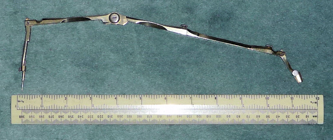
The joint in the fixed leg of the main compass with the extension fitted allows very large circles to be drawn whilst keeping the fixed pivotal leg in a near vertical position.
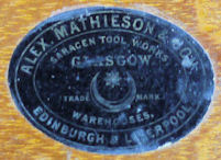
Mathieson's trade mark is on the box's interior bottom, seen by lifting out the tray, and helps to date this set. The Saracen Tool Works was in Glasgow from 1822 to 1966, they were makers of fine wood working tools: planes, mechanical, engineering, and edge tools. They opened premises in Edinburgh in 1856 and had premises in Liverpool at 8 Church Street from 1875 to 1910 and at 41 Byron Street from 1896 to 1924. The style of the instruments is mid to late Victorian; for example, the compasses use wood encased lead pencils, typical of 19th century sets.
Return
'Cadet' precision half-set by Temple Instruments Ltd of Wolverhampton. Bought in 1959 in Leeds, I used this set when I worked as a GPO Engineering Draughtsman in Newcastle-upon-Tyne from then until 1965.
Return
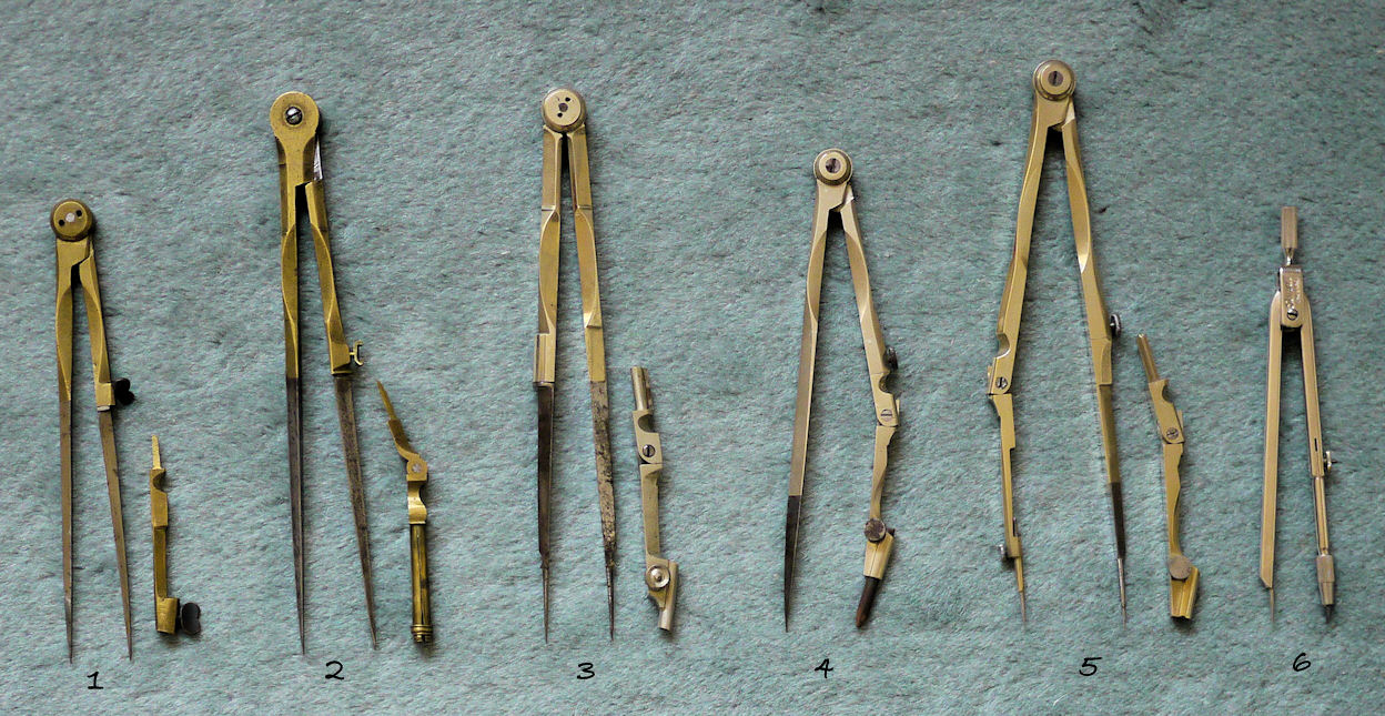
The development of the drawing compass
Compasses were originally dividers, they were only adapted to to receive pens and wood-cased black lead pencils from about the middle of the 18th century. The protractor is also a quite modern device for as P. J. Booker says, in A History of Engineering Drawing page 120, ... for until dividing engines were invented there was no readily available means of making them, at least not very accurately or cheaply. Angles, until well into the 18th century, had to be set out by compass, hence the reason for calling them mathematical instruments. Indeed the primary purpose of a compass was not to draw circles, which are but seldom required, but to accurately set angles, chords, sines, versed sines, tangents, secants, and to accurately divide lines into equal parts.
1. This is the brass late 18th century compass from my small Kiel case, identifying points are the large butterfly screws. The style of pencil holder was introduced in German compasses in mid century but not adopted in Britain and France until the mid-19th century.
2. One can see in this compass why London was established as the foremost instrument centre from the mid 18th century. The pencil point (initially called a crayon point) is jointed, allowing the pencil to be kept near vertical. However, the tubular pencil retainer was not the best solution as short stubs of wood encased pencils were difficult to remove if inadvertently knocked in, it persisted into the early 19th century. The compass joint, known as a long joint, has steel inserts. The small butterfly screws are typical of 18th century English compasses.
3. This is a London made compass in electron, circa 1860-1880; it has a sector joint recommended by Stanley and also the retaining screws have been eliminated with self-adjusting push joints. However, the solid rigid triangular fixed leg is still retained although modified with short steel needle points.
4. Typical mid to late 19th century compass with 3/16 inch pencil. This is not part of a set, but was probably bought as a single item as was very common. Full cased sets were quite expensive.
5. Late 19th century imported compass with short joint. Note the jointed fixed leg.
6. Mid 20th century in stainless steel.
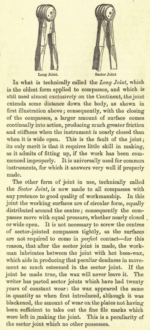
An explanation from the instrument maker William Ford Stanley in the 5th edition of A Descriptive Treatise on Mathematical Drawing Instruments, 1878. However, there are some excellent long-joint compasses and one has to bear in mind that Stanley attached his catalogue to his treatise in which he advertised his wares which, needless to say, were sector jointed.
Return
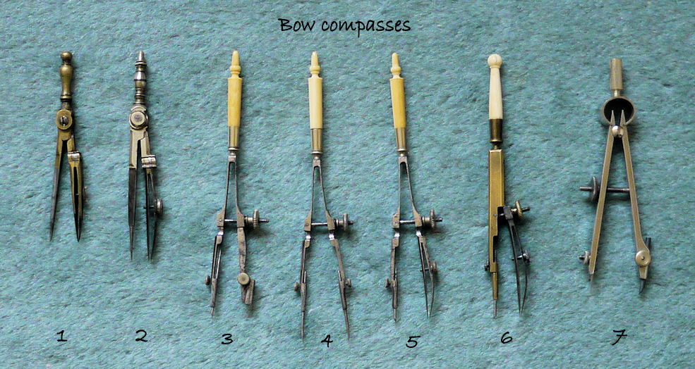
Large compasses are difficult to set accurately for small radiuses, hence the need for bow compasses, particularly when sub-dividing short lines.
1. 18th century London small compass.
2. English, electrum and steel legs with a brass handle, circa 1850.
3,4,5. Set of late 19th century steel spring-bow compasses with electrum and ivory handles.
6. This is an electrum and steel mid-19th century 'hair divider', the spindle is of ivory set in brass.
7. Stainless steel, mid-20th century.
Return
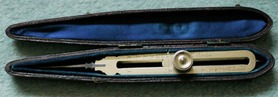
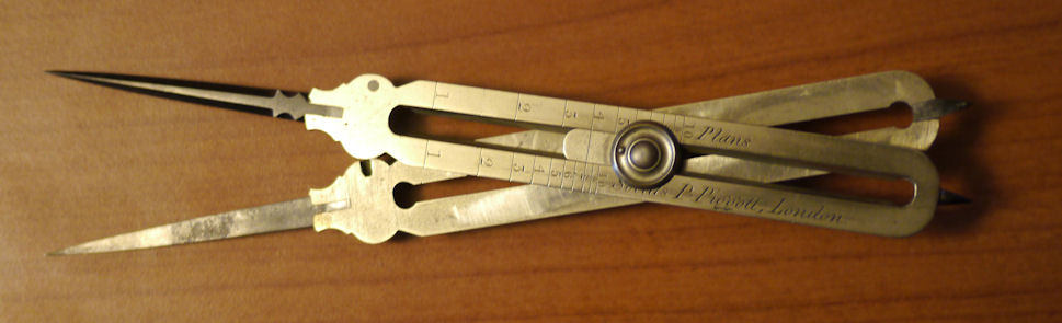
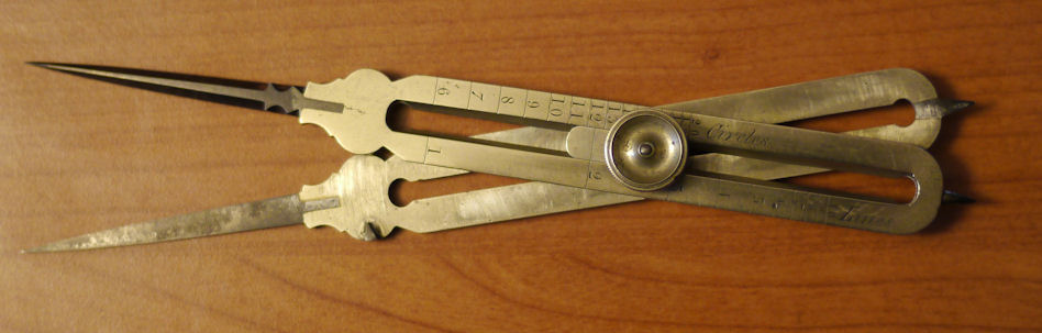
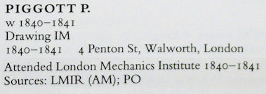
A proportional compass (160 mm) in a velvet lined case with a blue silk lined lid, brass with steel points, with four scales: circles, lines, plans, and solids, signed P. Piggott, London. Circa 1840-1841, according to the entry for P. Piggott in the Dictionary of British Scientific Instrument Makers 1550-1851:
Return
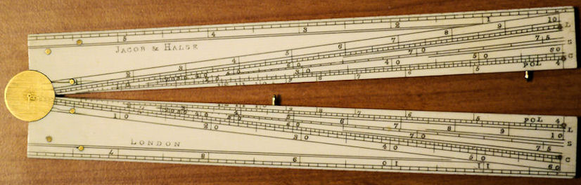
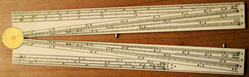
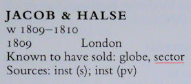
This is an ivory sector which was made and sold by Jacob & Halse in 1809. This precision instrument, the forerunner of the slide rule, can be narrowly dated because the partnership of Jacob & Halse only lasted for a brief period. They are listed in the Directory of British Scientific Instrument Makers 1550-1851:
Return
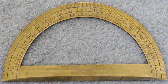
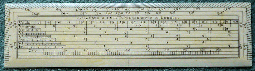
A fine Edwardian ivorine protractor in near perfect condition engraved J. Halden & Co. LTD Manchester & London. Halden's were incorporated as a limited company in 1907. It has two sets of diagonals, the right hand one being half the scale of the left one.
Return
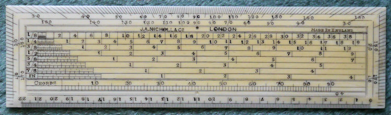
This is a late Victorian bone protractor made by J. A. Nicoll & Co.
Return
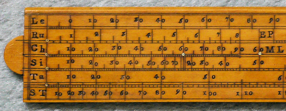
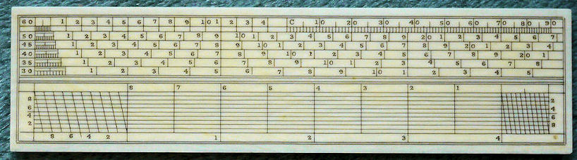
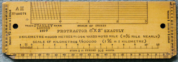
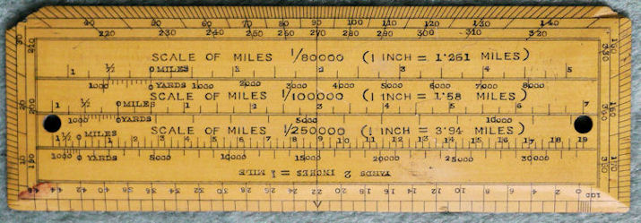
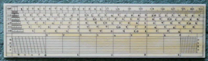
This is a First World War boxwood protractor made in 1917 for the army by Stanley of London. It has scales in miles for ordinance maps and also scales in kilometres for French maps. In Instruments of the Imagination: A history of drawing instruments in Britain 1600-1850 Howard Dawes says (page 8) ... during the 17th and the beginning of the 18th century it was common practice to use the system of diagonals marked on the rule to obtain two decimal places of measurement. But the diagonal lines continued to be placed on scale rules throughout the 19th century and well into the 20th, as can be seen here.
No one now seems to know how these scales were used, judging from the bewildering descriptions on instrument dealers' sites. Here is how a diagonal scale measurement was taken, consider the following enlargement of the Stanley protractor:
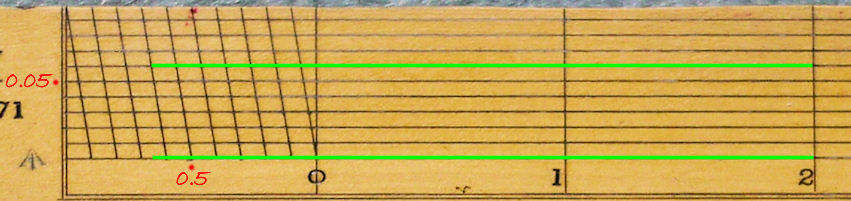
We want to determine the exact length of a line taken with a pair of dividers, we see that it measures roughly between 2.6 and 2.7 inches on the one-inch scale. Placing one leg of the dividers at 2 we see that it overlaps 2.6 (bottom green line). All we do now is step up vertically until we find the closest point of intersection, in this case at 0.06 (the upper green line)... so the line is 2.66 inches long. The horizontal lines are in tenths of an inch, the verticals then give a tenth of a tenth, points 0.5 and 0.05 are marked here in red. Any quantity could be scaled not just inches, scaling a half-inch would give two-hundredths of an inch, similarly tenths of a quarter inch would give four-hundredths of an inch and so on.
But they weren't of much practical use simply because British measurements weren't in decimals, but in 1/4, 1/8, 1/32, and in engineering, 1/1000 of an inch. This is what Stanley had to say about them in 1878 in his A Descriptive Treatise of Mathematical Drawing Instruments
The diagonal scale, now nearly obsolete, was foremerly one of the most universal mathematical scales; it is still placed, as a matter of form, on the protractor supplied with most cases of mathematical instruments. Theoretically, it is a very ingenious scale; practically, it is an almost useless one - the only purpose to which it is now applied being to a scale for the beam-compasses, which to be of any use, should be divided upon metal.
Return
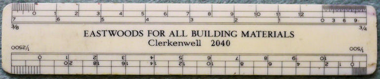
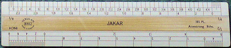
Typical of an advertising scale ruler, mid 20th century, these were given away free to drawing offices, usually with New Year calendars. Note the low telephone number: Clerkenwell, London, 2040. This ruler complemented my Jakar and was part of my working set. Scales are: 1/8 - 1/4 - 1/2 - 1 inch, and on the reverse 3/8 - 3/4 - (and the reason I required it) 1/500 and 1/2500.
A high quality scale ruler by Verulam, mid 20th century. I used this daily when I was a draughtsman. Eight scales: 1/8 - 1/4 - 1/2 - 1 inch on this side and 3/8 - 3/4 - 1½ - 3 inch on the reverse. This type of scale killed the need for diagonals and the need for a pair of dividers to determine or scale a line, as required with the Victorian and Edwardian examples above. The edges of the scale are tapered ovally to a thin edge which is placed directly on a drawn line to be measured or on a map. Zero of the scale is placed at the beginning of the line and the nearest number below the full length noted (if it falls between 4 and 5 say, 4 is the required number). The scale is then slid along until 4 coincides exactly with the end of the line, fractions are then read off directly from the start point now to the side of zero. This just about ended the strict need for a pair of dividers and drawing instruments were no longer called mathematical instruments except for historical conformity.
Return
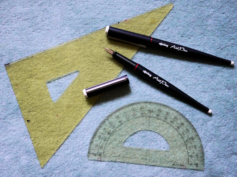
Set square, protractor, and two professional Rotring lettering pens, fine and medium. All mid 20th century. I bought the protractor in Leeds in 1956.
It may seem surprising, but such a simple instrument as the triangular set-square, as opposed to the twin-bladed square, was only in general use by draughtsman from about 1850. Thomas Bradley, in his Practical Geometry published in 1836, gave a detailed list of drawing instruments but made no mention of the triangular set-square. The main instruments in use from ancient times were the compass and the straight edge, the only tools needed in Euclidean geometry; the twin-bladed set-square came to the architectural draughtsman from its use by carpenters and stone cutters.
Return
Calculating instruments
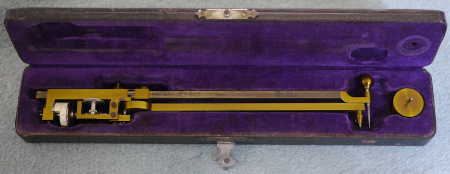
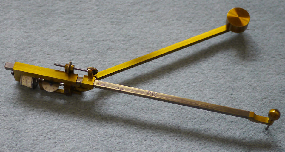
An Amsler proportional polar planimeter, serial No. 27650, dating from the 1890s. A high precision instrument and a rare item. Polar planimeters were used to calculate the area of an irregular shape by tracing the outline. It was invented and manufactured by Jakob Amsler-Laffon, a Swiss mathematician at Zurich university, in 1854.
Return
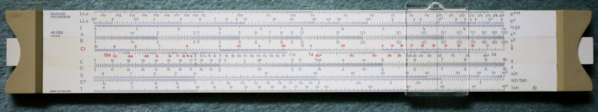
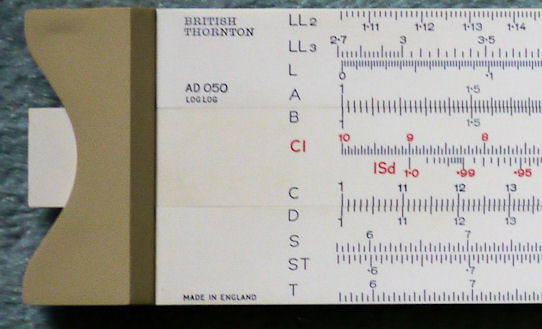
British Thornton AD 050 Log Log slide rule, blank on rear side. A. G. Thornton of Manchester became British Thornton in 1969.
British Thornton slide rules.
Return
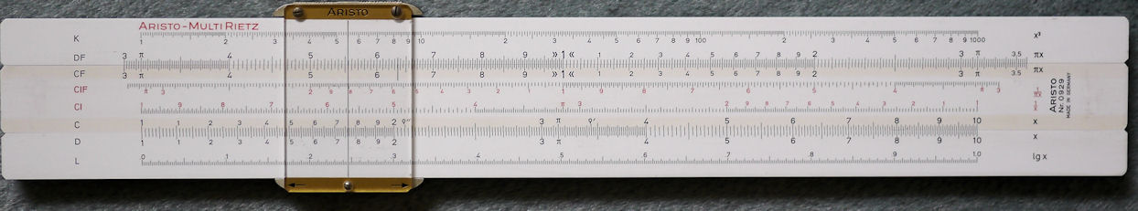
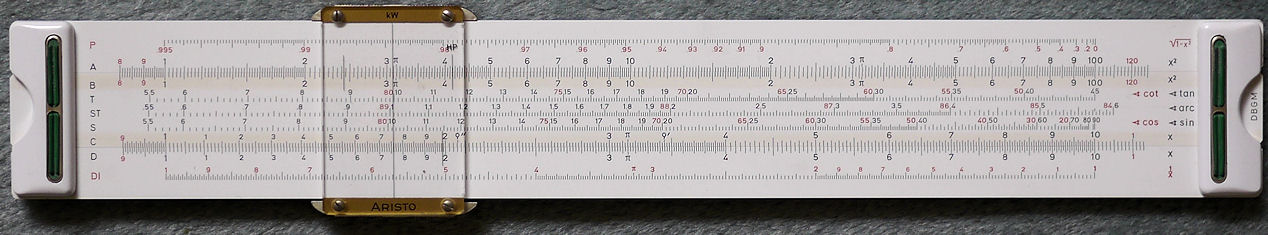
An Aristo MultiRietz Nr 0920 slide rule, this is an excellent example of the double faced slide rules produced by Aristo of the then West Germany. Aristo production stopped in 1978 when electronic calculators made slide rules redundant.
Aristo slide rules.
Bibliography
Booker, P. J. A History of Engineering Drawing, Chatto and Windus, 1963.
Bradley, T. Practical Geometry, Baldwin and Cradock, 1834. Thomas Bradley gives a full description of drawing instruments.
Clifton, G. Directory of British Scientific Instrument Makers 1550-1851, The National Science Museum and Zwemmer, 1991.
Dawes, H. Instruments of the Imagination: A history of drawing instruments in Britain 1600-1850, The Dawes Trust Ltd, 2009.
Hambly, M. Drawing Instruments, 1580-1980, Sotherby's Publications, 1988.
Heather, J. F. A Treatise on Mathematical Instruments 5th edition, John Weal, 1859.
Piedmont-Palladino, S. C. Tools of the Imagination: Drawing Tools and Technologies from the Eighteenth Century to the Present, Princeton Architectural Press, New York, 2007.
Rhead, E. L. Metallurgy, Longman, Green, & Co., 1895.
Return
Peter Ghiringhelli
2011
Home Page